Contents
Introduction
We’ll build a mobile robotic platform with a Raspberry Pi on a chassis. A Pololu DMC02 motor controller board is used to drive the engines. The controller receives serial commands from the Pi and sets power to the engines accordingly.
Parts
- Raspberry Pi.
- DMC02 motor controller. Other types will do, but this is the one we’ll use here.
- USB TTL serial cable.
- A chassis. A simple one like the Magician Chassis will do. We use the tracked Dagu Rover 5 Chassis here, with two DC motors.
- A rechargeable cell phone battery to feed the Raspberry Pi.
- Jumper wires (male-male).
- Lego, basic building blocks and plates. You can use all sorts of rubber bands and tie wraps or even build a more sophisticated casing, but you will want to use Lego for prototyping. Trust me.
- All thinkable components to make this an ongoing project, like a camera board, a powered speaker and an ultrasonic sensor.
The controller
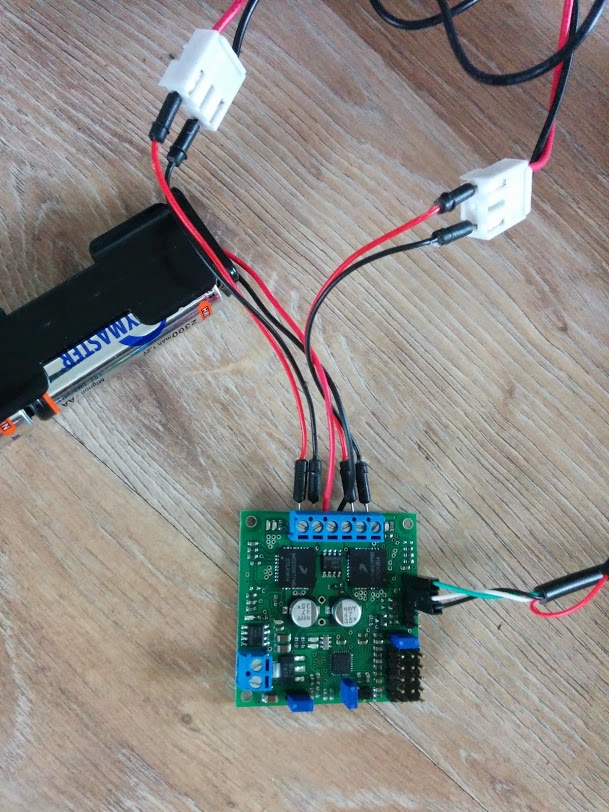
Connect the battery pack that comes with the chassis to the controller board. You can find the connection labels on the back of the PCB. Connect the black wire to GND adn the red wire to VIN.
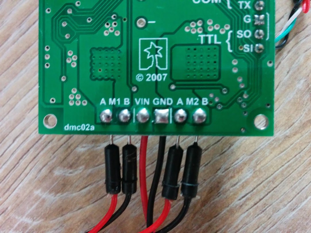
We make the Rover front-wheel-driven. We define the right motor as M1 and the left motor as M2. (Of course you may choose otherwise.) Use the jumper wires to connect the motors to the controller board. Connect the red wires to A and the black wires to B of M1 and M2 respectively. (Note: some chassis’ have the red and black wires swapped for one or both motors. It won’t do any harm. Simply connect red to black and black to red if the motor appears to turn in the opposite direction after sending a command.)
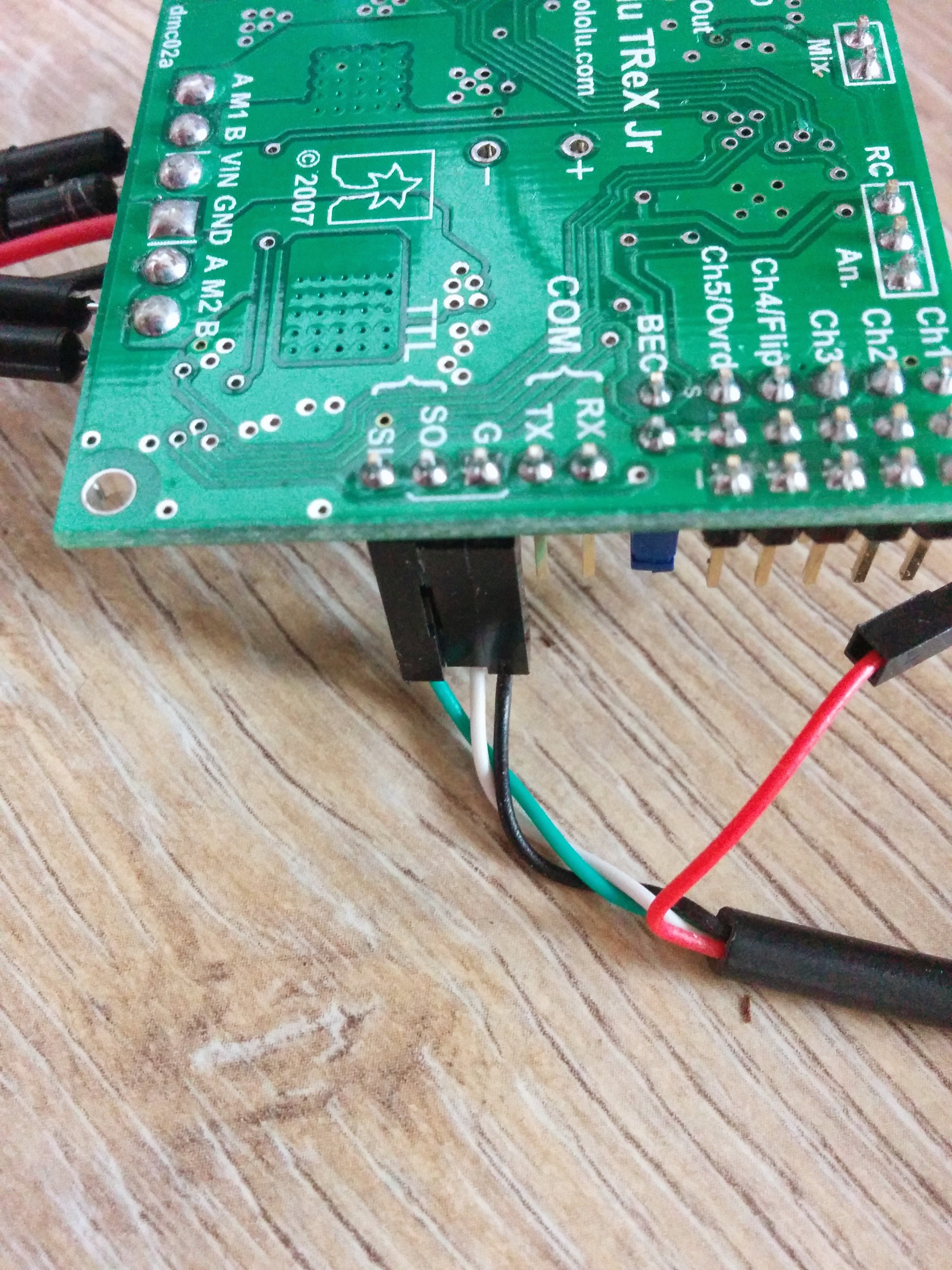
For the TTL cable, connect the black wire to G (ground), the white wire to SO (serial out) and the green wire to SI (serial in). Leave the red wire unconnected. Beware, in some TTL cables the green and white wires are swapped! (This is probably related to whether in and out are defined upstream or downstream.)
Test and tweak the controller
You can test this setup with the TReX Configurator for Windows. That is, if you’re lucky enough. The program did not run on my Windows 8.1 PC, but it did on my Windows 7 PC. (Sad enough for a Linux user. I’m still planning on writing a Linux tool for this.) Test the motors using the track location sliders on the Motor Control tab.
On the Parameter Configution tab, sub-tab Motor Params, set the PWM Prescaler to 8. Why? The controller uses pulse-width modulation to set the average voltage on the DC motor. A prescaler value of 64, for instance, corresponds to a PWM frequency of 2.44 kHz. This is an audible frequency and may lead to an annoying motor whine. A value of 8 gives a frequency of 19.53 kHz which you most likely won’t be able to hear.
Control the Rover programmatically
Now you can build it all together and show off your creativity with Lego. Connect the DMC02 to the Raspberry Pi. The device should appear in /dev, e.g. as /dev/ttyUSB0.
Take a look at the TReX Jr command documentation. Commands consist of one or two bytes. In the latter case the second is a data byte. As M1 is the right motor and M2 the left, we now have the following commands to set the motor speed and direction:
Right forward: 0xC2
Right backward: 0xC1
Left forward: 0xCA
Left backward: 0xC9
The command is followed by a data byte for the speed. Unfortunately ‘speed’ is not realy speed, but more like traction. The actual speed depends on other factors like traction on the other motor, friction and battery charge. You’ll want to experiment with this value and maybe convert it to suit your needs.
So now you can control the engines from the Pi. Let’s go for a little test drive in Python.
#!/usr/bin/python import serial import time ser = serial.Serial('/dev/ttyUSB0', 19200, timeout = 1) def forward(speed): command_right = chr(0xC2) command_left = chr(0xCA) ser.write(command_right) ser.write(chr(speed)) ser.write(command_left) ser.write(chr(speed)) def backward(speed): command_right = chr(0xC1) command_left = chr(0xC9) ser.write(command_right) ser.write(chr(speed)) ser.write(command_left) ser.write(chr(speed)) def stop(): command_right = chr(0xC2) command_left = chr(0xCA) ser.write(command_right) ser.write(chr(0)) ser.write(command_left) ser.write(chr(0)) def rotate_left(speed): command_right = chr(0xC2) command_left = chr(0xC9) ser.write(command_right) ser.write(chr(speed)) ser.write(command_left) ser.write(chr(speed)) def rotate_right(speed): command_right = chr(0xC1) command_left = chr(0xCA) ser.write(command_right) ser.write(chr(speed)) ser.write(command_left) ser.write(chr(speed)) forward(95) time.sleep(1) rotate_right(90) time.sleep(1) forward(95) time.sleep(1) backward(95) time.sleep(1) stop() |
So there’s our software-controlled Pi Rover. Move on from here. The fun has just started.
I have a similar setup. I am using the DMC01 connected go a Rasp Pi 2 via USB to TTL.
I used your code in Python 2 and it worked wonderfully. I am trying to get this working with a PS3 controller. I currently have the PS3 controller paired with the Rasp Pi via a Bluetooth dongle.
Would you have any idea how to setup the code to have the PS3 controller control the DCM01?
You can use Pygame to read from the PS3 controller. Then send the appropriate commands to the motor controller.
https://goo.gl/SYz41C
https://www.pygame.org/docs/ref/joystick.html